In the first part of our reverse engineering series, Getting Started on Reverse Engineering from Scan to CAD, we discussed how 3D scanners measure complicated features and surface geometries to help designers and engineers figure out the design intent of a manufactured part.
There are two types of 3D measurement equipment commonly used for reverse engineering to capture 3D measurements of a part due to their affordability, portability, and versatility:
- Contact 3D scanners: for example, portable CMMs and optical CMMs with a contact probe 1
- Non-contact 3D scanners: for example, laser or structured-light 3D scanners
The reverse engineering workflow is different for the two types of measurement tools, each with its advantages and drawbacks. Deciding on which one is best to use to transform 3D scan data to CAD really depends on a number of factors, including the type of material you are scanning, the complexity of the part, and your particular scenario.
Contact 3D Scanning Systems: Reverse Engineering As You Go
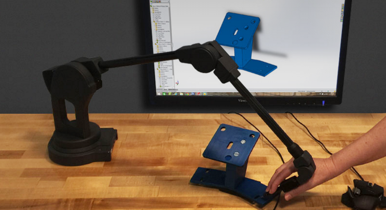
A MicroScribe portable CMM is used to collect 3D measurement data of a reference part. This reverse engineering workflow requires the user to scan the object and create the new CAD model simultaneously.
How Contact 3D Scanners Work
Traditional CMMs were invented in the 1960s 2 where operators were restricted to use them in a stable controlled environment. With the invention of portable CMMs in the 1980s, the new technology gave people the accessibility of bringing measurement tools to the shop floor.
It’s quick and simple to take measurements using portable CMMs. They are called point-based systems because you just need to touch the object with a probe to collect one measurement point.
SCAN to CAD Process
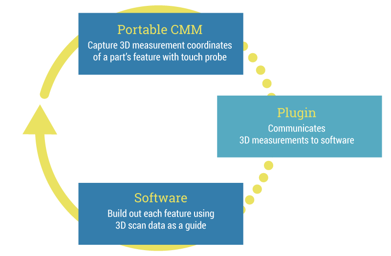
When reverse engineering with a portable CMM the data collection and the design process is done at the same time. The portable CMM is connected to a CAD modeling software (e.g. SOLIDWORKS) or reverse engineering software (e.g. Geomagic Design X). Depending on the software, sometimes a third party plugin is required to help make the direct connection between the portable CMM and the software.
As you collect surface measurements using a probe, the 3D coordinates are immediately collected into the software. You build each feature of the part as you go until you completely finish building the complete CAD model.
Reverse Engineering a Plastic Bottle
This video demonstration illustrates the process of reverse engineering a plastic bottle using a portable CMM with SOLIDWORKS CAD modeling software. The CAD model can be used to develop tooling for manufacturing or to create packaging or labels.
Advantages/Drawbacks
Using this method for reverse engineering is especially efficient for jobs where:
- you don’t need too many scan data points from the reference object in order to build CAD model
- you are measuring a part with reflective/dark surfaces, without part preparation
(non-contact 3D scanners use light as a projection source so they will have difficulty scanning this type of surface without coating the reference part first with a white powder) - the part geometry is simple or contains basic features such as sheet metal and machined parts
- the part has prismatic features or distinguished features such as circles, polygons
- the part has many holes or undercuts
CAD modeling/reverse engineering software often have deviation analysis functionality. This type of reverse engineering workflow gives users the ability to compare and analyze the newly created CAD against the physical part in real time by using the probe by taking actual measurements of the physical part. The advantage is that it gives users instant feedback on the quality of the created CAD.
One of the limitations to using a portable CMM for reverse engineering is that it is a contact measurement device, so it’s not the best for measuring fragile parts that can be damaged by the touch probe.
Non-Contact 3D Scanning Systems: Reverse Engineering Step-by-Step
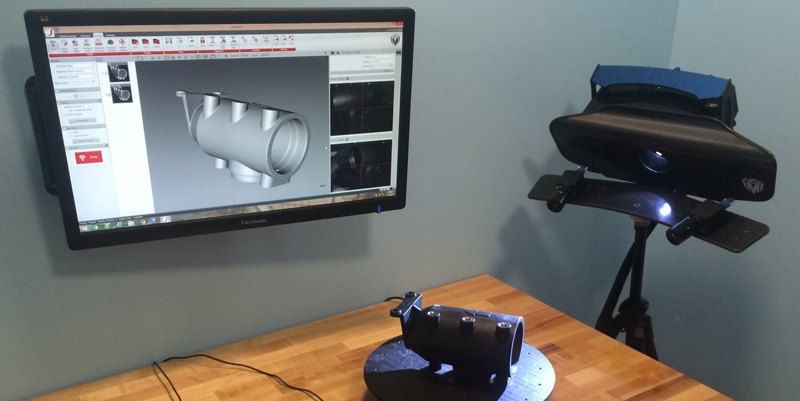
Capturing 3D measurements of an entire part using the HDI 3D Scanner. Once this process is complete, the scan data is imported into a software to create the CAD model.
How Non-Contact 3D Scanners Work
Non-contact 3D scanners are still considered relatively new up and coming technology when compared with contact 3D scanners. Contact 3D scanners are perceived as a more established form of measurement equipment compared to non-contact based 3D scanners due to its legacy.
A non-contact 3D scanner, such as a structured-light 3D scanner, is a great measurement tool when you need to gather more intelligence from the reference object in order to reverse engineer the part. While portable CMMs collect points one by one, non-contact 3D scanners capture a snapshot of the 3D surface measurements of a part in one scan. A structured-light 3D scanner can collect a million 3D coordinate points in one second without any physical contact with the object.
SCAN to CAD Process
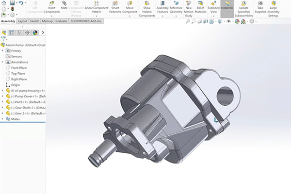
Reverse engineering using this method is a sequential process. You first have to capture all 3D scans of the entire part with a 3D scanner, then clean up the scan data before you start the process of creating the CAD model. The scan data is used as a visual reference to sketch the features of the part until the final CAD model is completed. Similar to using a portable CMM, sometimes a plugin is required to provide extra tools inside CAD modeling software (e.g. SOLIDWORKS) to help with the reverse engineering process (e.g. XTract3D or Geomagic for SOLIDWORKS).

Reverse Engineering an Automotive Part: Transforming Scan Data to CAD
This video illustrates the reverse engineering workflow of using a non-contact 3D scanner, specifically a structured-light 3D scanner, and later importing the scan data into SpaceClaim software for CAD modeling.
Advantages/Drawbacks
Non-contact 3D scanners are great for measuring parts:
- with extremely complex surfaces (organic/freeform shapes) that would be a challenge for portable CMMs to take measurements
- Cannot be touched (antique or fragile parts with no existing CAD model)
This method of reverse engineering takes more time collecting measurement data compared to using a portable CMM. However, you will have more information to learn and analyze the construction of the existing part for building the new part. You will also have more data for deviation analysis by comparing scan data with the newly created CAD model.
A drawback is that if the reference part has dark, shiny, or reflective surfaces, you will have to coat the object before you can begin the 3D scanning process. In contrast, you don’t need to do that with a contact 3D scanner.
Which Option is Right for Me?
On the surface, it might appear that using a non-contact 3D scanner would be a better solution since it captures more data, but more data isn’t always better.
If you just need to capture a few measurement points from the reference part for reverse engineering, a contact 3D scanner such as a portable CMM might be the right tool for you because it’s quick and efficient.
If a part contains complex organic shapes and you need to capture measurements of an entire part for reverse engineering, non-contact 3D scanners would be your best bet.
Is one type of scanner better than the other? Not necessarily. Contact and non-contact scanners provide the same outcome (create CAD model from 3D scan data) but sometimes one tool might be better suited for a particular job.
Here is a summary chart to help you decide which type of scanner would be best for your application:
| Contact 3D Scanner (Portable CMMs/Optical CMMs) |
Non-Contact 3D Scanner (Laser/Structured-light 3D scanner) |
|
|---|---|---|
| Measurement Type | Probe to touch the object in order to collect measurement points | No physical contact with the object is necessary to collect measurement points |
| Examples | MicroScribe, Kreon | HDI, Artec |
| Reverse engineering workflow | Multitasking: You probe and create CAD model as you go |
In Sequence:
|
| Collect Data Points | Point-based: Use the touch probe to collect one coordinate point at a time |
Point clouds: Capable of acquiring millions of coordinate points per scan/in one second |
| Types of application | Great for jobs with prismatic parts, when you only need to get a few 3D coordinates to build CAD model | You need complete scan data of physical object to reverse engineer a part, typically when the part has more complex geometry |
| Benefits | Quick and efficient, easy to take quick measurements, easily measure inside of objects (holes) | By capturing scans of the entire object, you have the ability to get more intelligence on the reference part to better understand design intent (compare more scan data with CAD to see deviation) |
| Drawbacks | Not good at scanning things that cannot be touched like fragile parts | A longer process as more time is taken for data collection and cleanup; need to prepare dark, shiny, and reflective parts before scanning |
| Good at these challenging materials | Better with reflective/dark surfaces (without treatment) like sheet metal, rigid, typically distinguish features (circles, polygons) | Complicated parts including those with organic shapes |
| Tradeoffs | Speed for information: Less information from the reference object compared to using non-contact 3D scanner | Knowledge for speed: Know more about the physical part but the process takes longer compared to using contact 3D scanner |
Keep posted for part 3 of our reverse engineering series where we’ll compare parametric CAD modeling with direct modeling.
– – –
References:
- Traditional CMMs are also an example of contact 3D scanners but in this blog post, we will only cover portable CMMs due to their affordability, portability, and versatility.
- Source: Design Engineering: A History of Metrology

Reverse engineering is needed to analyze the good and bad features of competitors’ product. Thanks for sharing the workflow of reverse engineering.
Thanks Ramakrishnan for your comment. While you pointed out one of the reasons for reverse engineering, there are other advantages to using reverse engineering that doesn’t involve competitor’s products. You can read more about it in our article, Getting Started on Reverse Engineering from Scan to CAD.
I thought it was really interesting how you explain that there isn’t really one scanner that is better, but one may be better suited to a job. To me, it would be helpful to have professionals in reverse engineering determine this so that you get the best result. I’ll have to look more into reverse engineering.