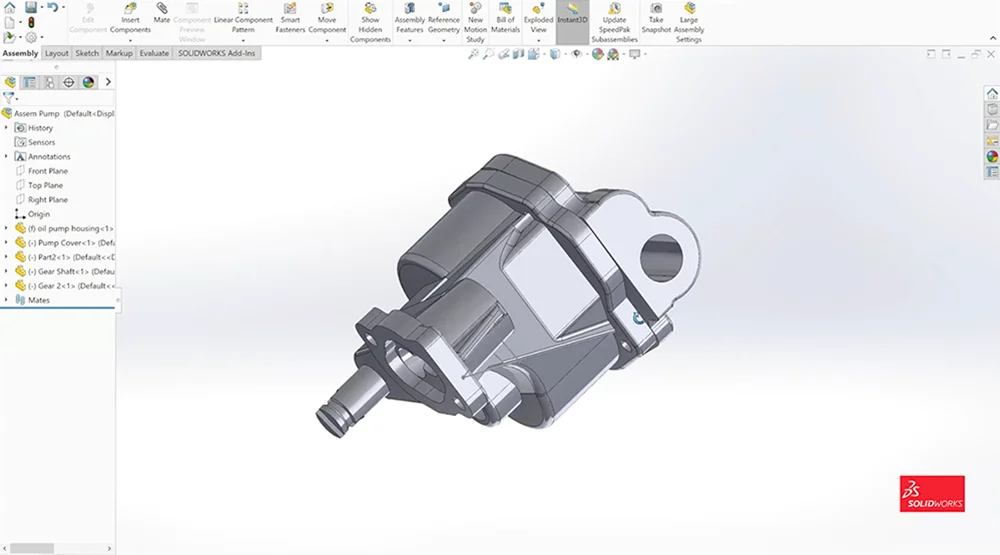
In my 15+ years of working in the 3D scanning industry, I had completed many reverse engineering projects (for work and for personal projects as I love rebuilding cars). To be completely honest, I have spent plenty of time doing it the wrong way. I had to redo parts and wasted countless days and sleepless nights trying to figure out what is the most effective way of reverse engineering an existing part into parametric CAD.
I created this detailed guide because I want to show you all you need to know about the Scan to CAD process. Hopefully, this will help you avoid the mistakes I’ve made. It was trial and error that ultimately led me to come up with the best practices of reverse engineering.

I want to give you insights into the best ways of reverse engineering a part using an oil pump as an example. It’s a great demo part as it has multiple components with complicated features as well as simple parts. It’s a mechanical assembly that has a lot of commonality to the parts I normally need to reverse engineer.
The process is also known as Scan to CAD, in which:
I’ll be answering all these questions here.

I’ve created a video series you can follow along. It’s essentially a step-by-step guide to the entire Scan to CAD process. Along with these videos, I will highlight the takeaways from each step.
These are the basic steps of Scan to CAD:
Here is a preview of the video series so you can get a better sense of what I’ll be covering:
I want to use SOLIDWORKS as the CAD software to illustrate the SCAN to CAD process. The reason is that it’s one of the more popular CAD programs out there. It’s quite amazing to know that there are more than 6 million people using SOLIDWORKS.
To provide us with more tools to reverse engineer this part, I use a plugin that works natively inside SOLIDWORKS called Mesh2Surface. It has a lot of great Scan to CAD tools that work in synergy with the ones already available inside SOLIDWORKS.

Even before opening up SOLIDWORKS, it is crucial to understand Design Intent.
Design Intent is understanding the purpose of this part in terms of its function and how it relates to the other components of an assembly in order to build the part correctly.
Questions that help you figure out Design Intent of a part:
Whether the part we are reverse engineering is as complex as a jet engine or as simple as a pencil, we will first need to answer these questions in order to help guide decision-making throughout this entire process. This will help us decide on things like what we use for alignment, what features we want to reference, and how we can accomplish the goal of recreating the part to our intended goal.
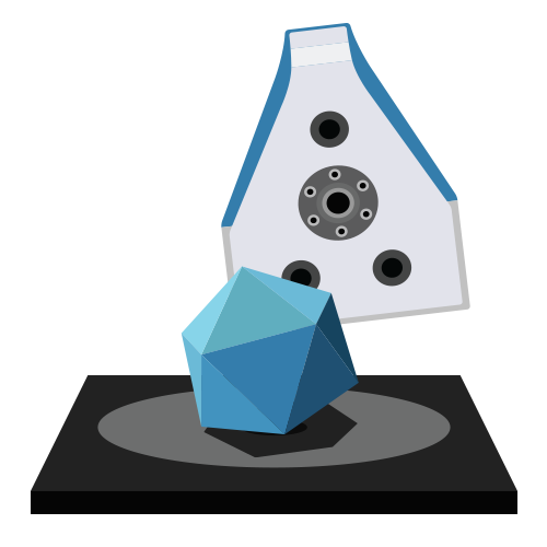
There’s often a common misconception that a 3D scanner can output a CAD model which is not true. You might look at this at first and think it’s complicated to use scan data as a starting point for the design. But it’s actually not.
The key is to break down this Scan to CAD process into smaller more manageable components and build out the design. The benefits far outweigh the work than if you have to design something like an oil pump completely from scratch. Designing this way is especially useful when there are multiple components of an assembly or if you have an organic freeform object.
The Scan to CAD approach to design almost feels like tracing a drawing. You are essentially using the scan data as a visual reference for design.
You need accurate 3D scans in order to reverse engineer parts to the highest accuracy of the physical part. This all depends on the accuracy your 3D scanner is capable of achieving (ie. consumer vs. professional systems). Your output is only as good as your input. Even if you have a professional high accuracy 3D scanner, ensure it is operating at optimal conditions (ie. temperature) to capture the best scan results.
There’s no need to capture every single nook and crevice of the part. Capture the pertinent information you need to reverse engineer the part to save you valuable time.
There are tips and tricks to make your 3D scanning process much smoother. For example, using a rotary table makes it much easier on yourself as you don’t have to walk around the object to scan. Instead, you spin the object and hold the 3D scanner in place.
We put together A Guide to the Best 3D Scanning Accessories. It includes tips on things you can use around your office for object fixturing and 3D scanner alignment to get the best quality scans.

A Guide to the Best 3D Scanning Accessories
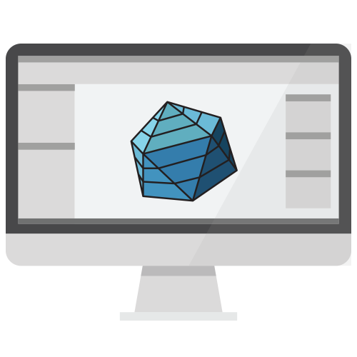
How you set the part up at the very beginning is important because you will build it around the central feature or function.
For instance, one of the most critical aspects of reverse engineering comes in the initial alignment phase where we take a part and align it to the world coordinate system. The initial features or Datum that are used should be the primary focal point of the part. This is because this feature will be what the recast of the part’s measurements and features are based around. The initial alignment of a part to a world coordinate can give you speed advantages to the entire process or cause a massive slow down depending upon if the correct features are used or not.
I can’t emphasize this enough. To really understand the order of operations of the entire reverse engineering process, you need to know how the part functions at the beginning of the process. This goes back to what we’ve talked about regarding Design Intent and how it guides you through the entire Scan to CAD process. If you don’t do this correctly, you will spend a lot of time redrawing the part as I have done many times in the past.
Most of the time, these are the steps that are usually involved in building out the basic reference geometry:
Create a cross-section of the scanned part
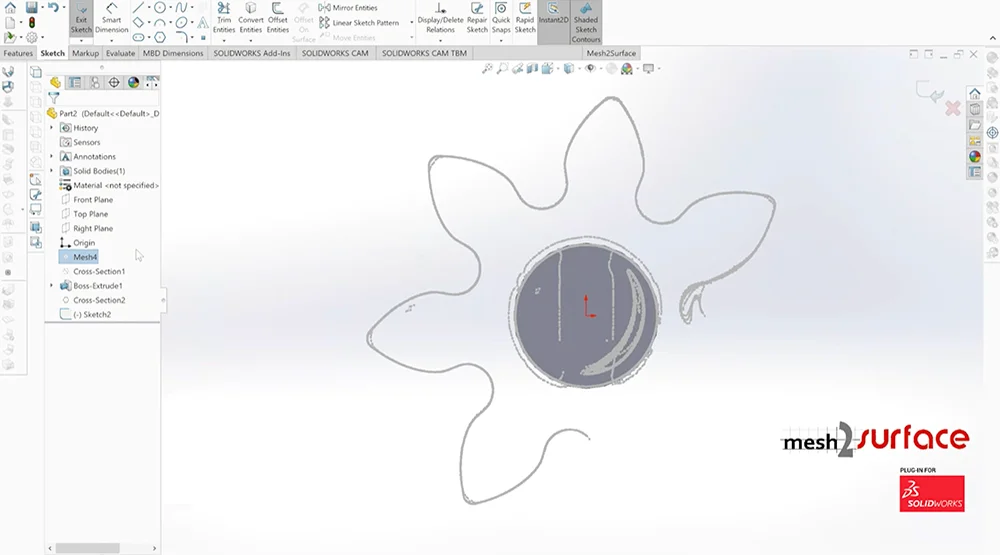
Sketch the 2D profile
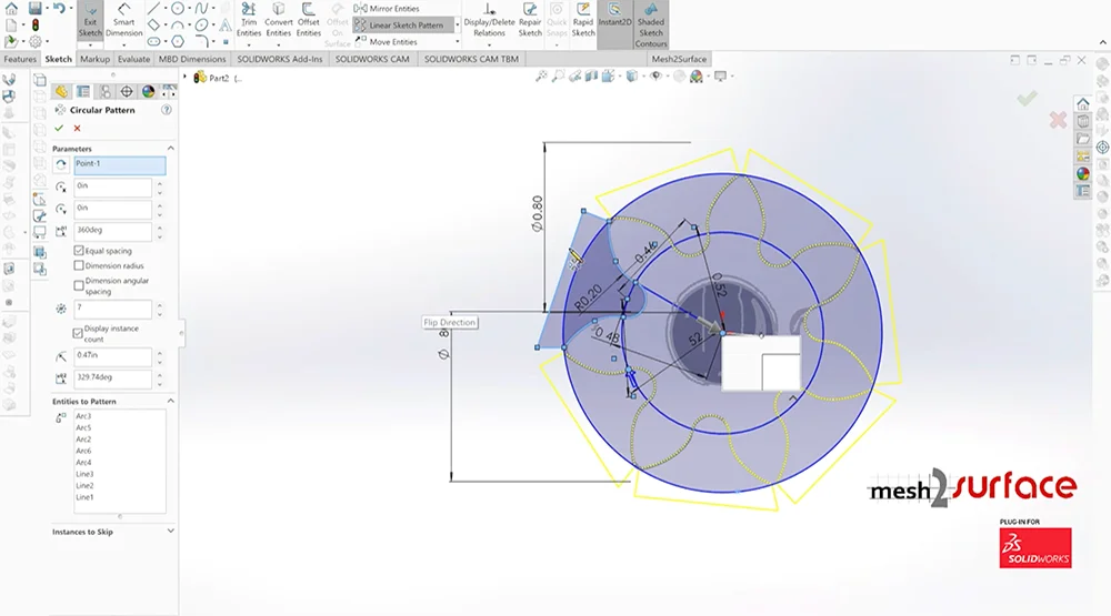
Revolve, extrude, merge, and/or trim the geometries together until you get a nice clean CAD.
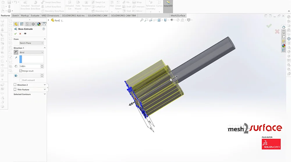
Once you’ve done it a few times and get a hang of it, it gets easier and easier.
When you first look at reverse engineering a complicated part like an oil pump, it can be overwhelming at first. However, if you first focus on breaking down into shapes (spheres, circles, cylinders, arcs, etc.) and build out the basic structure of the part, you can then later go in and fine-tune the exact measurements when you are finalizing the part.
Depending upon the part that needs to be made, whether it was originally made in CAD or if you are drawing this part up in CAD for the first time, it is important to get the most critical aspects of the part out of the way first. There are core details that will be important and other features that are not as important. Having an idea of what these things are will greatly help in setting up an order of operations to create a model that is accurate without wasting time going back and redoing steps over and over again.
A manufactured part can never be as perfect as a CAD model (reality vs. concept). Oftentimes, the scanned data you are getting is from a part that is worn over time so it’s not in the pristine condition it once was right out of manufacturing. Even if it’s right out of production, manufacturing can never create anything that is as perfect as a CAD model.
In the Scan to CAD process, you need to decide on what you want to keep and what needs to be adjusted for your application (Design Intent). What parts of the object or assembly are the most critical?
Do you want to:
More frequently than not, you should choose the second option as you are redesigning the part for current use.
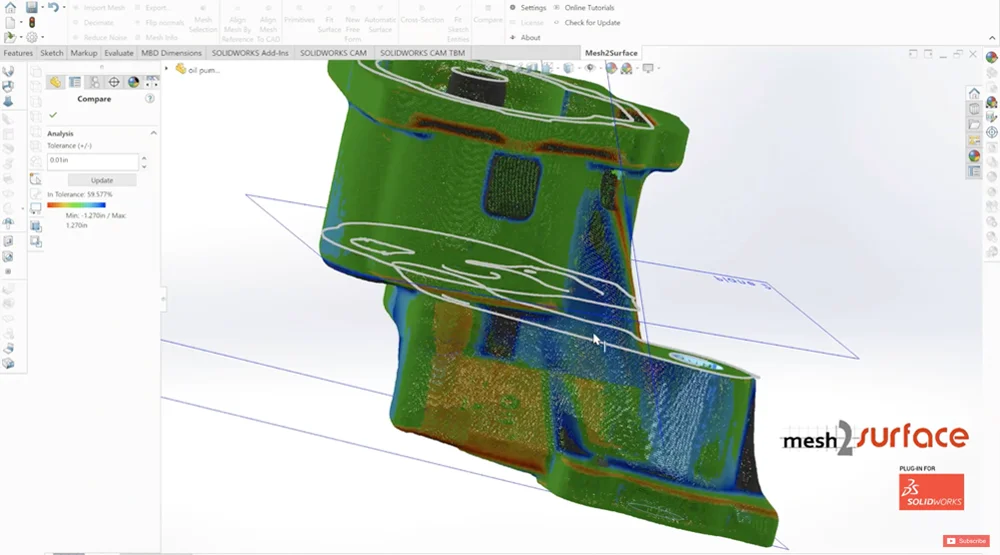
Because we’re using Mesh2Surface for SOLIDWORKS, it has a color deviation map where I could easily see how accurate I was building out the model as compared to the scan data.
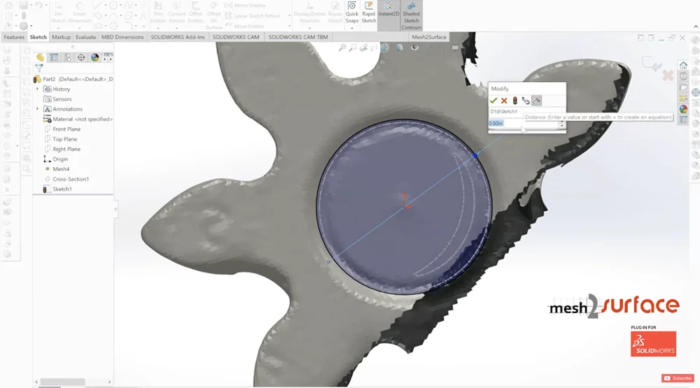
There are times when you have no control over the quality of the scan data because you didn’t scan it yourself and/or that is the only source data you have to work with. You can still use it to build out a CAD model as we demonstrated in video 4 if you have the scan data for the core features. It usually works well when you have a part that has symmetrical or repeating surfaces where you can infer how the missing scan portion should be.
SOLIDWORKS is foremost a CAD software, not a reverse engineering software, so it is beneficial to use a Scan to CAD plugin like Mesh2Surface. The plugin provides additional features and tools you can use directly inside SOLIDWORKS to do Scan to CAD functions that you normally can’t do with SOLIDWORKS by itself. Mesh2Surface helps you do reverse engineering in the most efficient way while making sure you get accurate results with the 3D comparison feature (mesh vs. CAD). It takes the guesswork out of reverse engineering and it’s a more robust method to make sure you get the results you need.
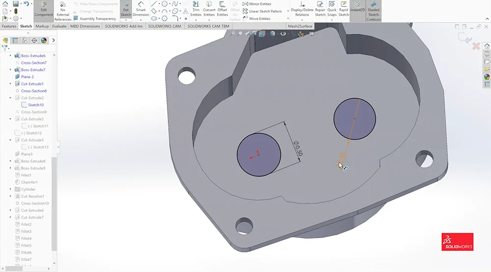
This is the stage where we make sure all the measurements are consistent so that individual components mate properly and holes are concentric to one another. For example, if the shaft is 0.5” in diameter, we need to make sure the hole that the shaft goes into will fit nicely with a 0.5” hole diameter as well (not 0.48” as I initially had it at).
When you are following scan data, you might get a hole measurement that is 5.984”. You just need to double-check all your measurements to make sure they are a nice number for manufacturing. In this example, we would make the hole diameter 6” instead of 5.984”.
However, if there should be clearance between two components this also needs to be considered. For instance, a shaft fitting in a hole may need a few thousandths of an inch of clearance to operate correctly and this all needs to be considered as well.
I built this assembly as a parametric CAD model using SOLIDWORKS so adjustments can be made pretty easily. If you are trying to replace an existing oil pump and you are doing this Scan to CAD process because you don’t have the original CAD or it never existed, then you would try to reverse engineer the part as close to the scan data as possible. If it’s for a new application, then you don’t have to follow to the tee to the scan data. As we’ve emphasized throughout this guide, the way you design it will be dictated by your application.
Even if we have a part that, on the surface, looks complicated because it has multiple components that make up the assembly, it’s pretty basic to reverse engineer it once we break down the process.
I hope you find this guide useful. If you have any questions about this process, feel free to contact me and I’ll be sure to answer them.
Cheers,