Can A 3D Scanner Directly Output A CAD Model?
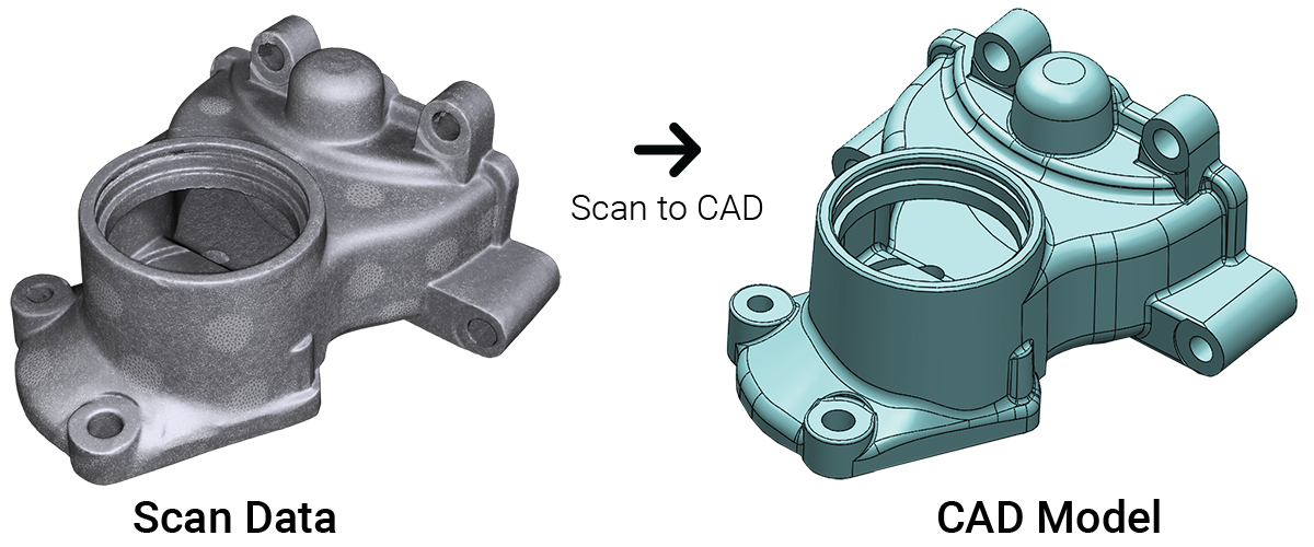
The short answer is no. A 3D scanner cannot directly output a CAD model. This is because a 3D scanner outputs point clouds or mesh data, which acts as a single entity that is not editable.

Let’s explain this concept using a camera as an example. A 3D scanner is just like a fancy camera, except instead of taking photos it captures scans of objects in 3D. If you take a photo of a car with a camera, you know that the photo has a car in it. However, your camera cannot interpret what exactly is in the picture. It only understands that the file is a picture. If you upload the photo into your computer to view it, likewise, the computer would only know that it is a picture, but not what the picture contains.
A 3D scanner is just like that. The computer program knows there is a scan but it has no idea what the scan is supposed to represent. You must interpret what the scan is. Then using CAD software on the computer, you sketch the object into a CAD model using the scan data as a tracing guide. Just like if you want to draw a realistic drawing of a car, it would be much easier to directly trace right on top of the photo than if you have to draw it from memory or just by looking at a photo.
Using scan data from a 3D scanner as a reference for design creates incredibly accurate CAD models. This process is known as Scan to CAD. You need this modeling step to bridge the gap before you can have a CAD model consisting of a solid CAD model with editable features, the design blueprint of the product for manufacturing.
This sounds rather complicated. Can you show me the Scan to CAD process?
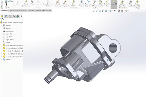
It’s actually not too complicated once you understand the basics. Sometimes it’s easier to explain this with a simple demonstration. In this video, scan data was imported into SOLIDWORKS CAD modeling software. Mesh2Surface for SOLIDWORKS plugin that works natively inside the CAD modeling program was used to reverse engineer the part.
If you are already a SOLIDWORKS user, it’s a logical choice to use Mesh2Surface for SOLIDWORKS that works natively inside the CAD software to easily reverse engineering objects from 3D scanner data to CAD.
Point cloud or mesh output by the 3D scanner provides pertinent surface measurements about the object’s surface geometry which is useful in creating a CAD model of the part. The scan data functions as a template in building the new CAD model.
Once you go through this modeling stage, your output is a CAD model (STEP or IGES) which is now ready for manufacturing.
Then why use a 3D scanner to create a CAD model if I have to recreate it anyways?
Designing from a blank canvas can be an overwhelming project to take on. You might not get it right on the first try and may take you many versions to get you to the final CAD model you are happy with. Why not leverage knowledge from an existing object and learn from it which will make your work much easier and more accurate?
Reasons why to Scan to CAD:
- It’s more efficient than designing from scratch
- It gives you an accurate representation of the existing part to create the CAD model
- It gives you the ability to insert design intention and fix problems or damage
Creating CAD models through the process of reverse engineering from Scan to CAD gives you insights into designing better products but also do it in a faster amount of time than designing from scratch. This is especially true for objects with organic surfaces. A 3D scanner makes reverse engineering faster and much simpler than if you have to do it without aids. Instead of trying to get complex curves and angles just right, reverse engineering gives the user the ability to snap onto the curve and create an identical profile. If the profile is incorrect or the physical part has any damage, then the designer has the power to see where the old geometry is and has the ability to correct it.


